Following these Guidelines Will Help you Find the Electical Problem With Your Tuttnauer Manual Autoclave
1. Disconnect power to unit.
2. Set sterilizer controls to the following settings:
- Circuit Breaker = ON
- Power Switch = ON
- Sterilizer Door = CLOSED
- Timer = Set for more than 10 minutes
- Temperature Controller = Set at 250º or higher
3. Set a multi-meter to ohm scale, then connect the line and neutral termi-
nals of the power module.
4. Rotate the Multi-Purpose Valve to each setting; starting and ending at O,
and observe the meter for the following:
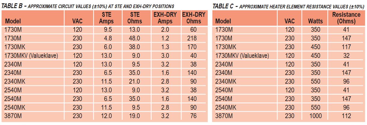
- In the STE and EXH+DRY positions, the meter should read the circuit values ( ±10%) shown in Table B, below for each model. If the meter reads a much higher resistance than shown in Table B, it is an indication of an open circuit. If the reading is significantly lower than shown in Table B, it is an indication of a short circuit or heater burnout.
- In the O and FILL positions, the meter should read a very high resistance – which indicates an open circuit.
5. Remove unit's covers and insulation blanket. Perform a full visual inspection of wiring, terminals and connections. Inspect the wiring harness for loose leads and broken or damaged wires. Make any repairs and retest. If no defects found, then inspect each component and conduct continuity check of the complete wiring circuit.
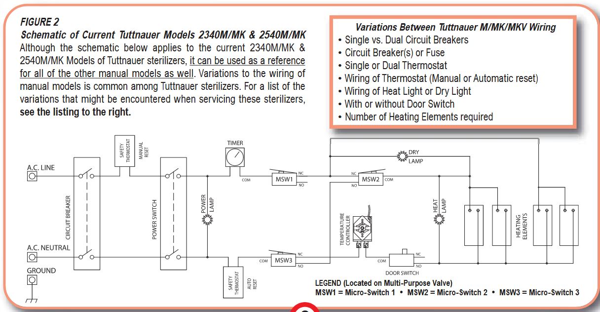
6. Refer to the schematic in Figure 2, below, check each circuit component, starting with the circuit breaker. Take note of the following char-
acteristics for each of the components:
- Safety Thermostats should be closed except at high temperature when they open to protect the circuit.
Note: Models built after January, 1993 have dual Safety Thermostats, one of which has a manual reset button and is located near the circuit breaker.
- Timer must be turned past 10 minutes to make contact and provide electrical continuity.
- Control Thermostat must be set above 212 ̊ F to make contact and provide electrical continuity.
- Micro-Switch positions and wiring are referenced on page 9, MULTI-PURPOSE VALVE & MICRO-SWITCHES. (Note: Micro-Switches are best checked with an analog ohm meter.)
- Heater element resistance values are shown in Table C, below.
7. Repair or replace all faulty circuits or components, then retest unit.
8. Replace insulation blanket and reinstall covers.
9. Run unit for several cycles and check all operations.

